Introduction
I decided to embark on this project because the app provided by my solar inverter was clunky and didn’t offer an easy way to connect to Home Assistant. I wanted a seamless integration that allowed me to have full control over my solar panels, especially to automate shutting them down when energy prices go negative. This guide will walk you through how I achieved this using an ESP8266, MODBUS communication, and Home Assistant, giving you the ability to efficiently manage your solar energy system.
Before we start a quick explanation of all the terms used:
- MODBUS: A communication protocol used for industrial automation and control systems.
- RS485: A standard defining the electrical characteristics of drivers and receivers for use in serial communications systems.
- ESP8266 or ESP32: Low-cost Wi-Fi microchips with built-in TCP/IP protocol stack.
- UART: Universal Asynchronous Receiver/Transmitter, a hardware communication protocol that uses TX (Transmit) and RX (Receive) for serial communication.
- RJ45: A type of connector commonly used for Ethernet networking.
- T-568B: A very common wiring standard for terminating Ethernet cables, specifying the pinout for the RJ45 connector.
Some of the product links in this article are affiliate links. I added them afterward to the mentioned items. Using these links helps support my work on articles like this one—thank you if you choose to use them! If not, no worries at all. 😊
Pre-requisites
To follow the steps in this blog post, you’ll need the following:
- Home Assistant: Ensure it’s up and running.
- Solar inverter with MODBUS communication support over serial RS485:
- Have the technical specification document of MODBUS for your solar inverter ready.
- This guide uses a SolPlanet inverter (specifications available in the app).
- ESP8266 or ESP32
- RS485 board to use with ESP8266 (recommended: MAX485 TTL)
- A spare ethernet cable for the RJ45.
Debugging
Before proceeding, verify that you can get MODBUS serial to work with your inverter. I used a USB RS485 board for easy debugging with a trial of Modbus Poll. I have wasted a lot of time starting directly on the ESP8266 instead of starting with some isolated testing.
Hardware Setup
For this solution, I used an ESP8266 with a MAX485. Alternatively, you can use a UART TTL to RS485 board with automatic flow control, although I found the more reliable. Setting up flow control on an ESPHome installation is just setting one configuration value.
Wiring
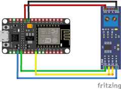
MAX485 to ESP8266
Follow the schematic for these connections:
- ESP8266 to MAX485
- 3V or VIN to VCC (I tried 3V but had to switch to VIN, be mindful that the USB on the inverter is NOT 5V)
- GND to GND
- TX to DI
- RX to RO
- D5 to DE & RE
Update the connections accordingly if you use an ESP32.
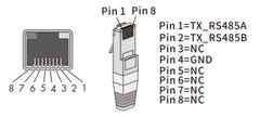
MAX485 to SolPlanet Inverter
The installation manual of my inverter contained a schematic to connect it through an RJ45 jack. I connected A to A and B to B. In my situation, the wire is very short, so I did not bother connecting ground. In a typical T-568B layout, that means white-orange to A and orange to B.
Software setup
Home Assistant
Ensure your Home Assistant is up and running. If not, set it up first. I suggest avoiding containers as they can be tricky with Home Assistant.
Setup ESPHome
If you do not already have it, add the official ESPHome add-on to your Home Assistant.
Once set up, install ESPHome on your ESP device using the getting started guide.
Setup Modbus
Once ESPHome is set up, add the configuration.
You’ll need to set up the MODBUS connection first. See the configuration example below with added comments for clarification.
esphome:
  name: solarinverter
  friendly_name: Solar Inverter

esp8266:
  board: esp01_1m

logger:
  level: INFO
  # On an ESP8266 you will NEED to disable serial logging
  baud_rate: 0

# There will be some Home Assistant and Wi-Fi configuration here
# ...

# Setup the UART connection
uart:
  id: mod_uart
  # On a Lolin board the TX & RX pins are 1 & 3
  tx_pin: 1
  rx_pin: 3
  # Follow your solar inverter's guide for the following settings
  # My inverter documentation specifies 9600 8N1 which means '8' data bits, no 'N' parity bit, '1' stop bit
  baud_rate: 9600
  data_bits: 8
  parity: NONE
  stop_bits: 1

modbus:
  id: modbus_connection
  uart_id: mod_uart
  # In the diagram we added the flow pins to GPIO 14 or D5
  flow_control_pin: 14

modbus_controller:
- id: modbus_device
  # The modbus device address to connect to, in the installer settings of my app it shows:
  # Modbus device address: 3 (update this accordingly, I recommend figuring this out during debugging)
  address: 0x3
  modbus_id: modbus_connection
  # Interval in seconds with which to poll all sensors
  update_interval: 15s
  setup_priority: -10

sensor:
# Here we will add the sensors

switch:
# Here we will add the switches
Translate the documentation of your inverter to the following template. A tip is that you can upload screenshots or text of the documentation to ChatGPT which may help you with transforming the documentation to YAML. The full yaml configuration for use with a SolPlanet ASW 5K-LT-G2 Pro inverter is available on my Github.
Sensor Example
Also, check out the ESPHome documentation for MODBUS sensors.
sensor:
- platform: modbus_controller
  modbus_controller_id: modbus_device
  name: "Today of inverter"
  # update the following fields to reflect the documentation
  register_type: read
  address: 1302
  value_type: U_DWORD
  device_class: energy
  unit_of_measurement: "kWh"
  accuracy_decimals: 1
  # the state class is only useful for day or all-time totals, otherwise remove
  state_class: total_increasing
  # the amount of intervals this sensor may skip, remove if you want to update every cycle
  skip_updates: 50
  filters:
  # multiply if necessary by following the documentation
  - multiply: 0.1
  # my sensor sometimes bugs to its max value, I fixed this by clamping to reasonable values
  - clamp:
      min_value: 0.1
      max_value: 7000
      ignore_out_of_range: true
  # select a nice icon to show in Home Assistant
  icon: "mdi:solar-power"
Switch Example
Also, check out the ESPHome documentation for MODBUS switches.
switch:
- platform: modbus_controller
  modbus_controller_id: modbus_device
  name: "PV Inverter ON/OFF"
  # update the following fields to reflect the documentation
  register_type: holding
  bitmask: 1
  address: 200
  # select a nice icon to show in Home Assistant
  icon: "mdi:toggle-switch"
Other Sensors
As of the time of writing, ESPHome also supports other types of sensors:
- Modbus Controller Sensor
- Modbus Controller Binary Sensor
- Modbus Controller Output
- Modbus Controller Switch
- Modbus Controller Number
- Modbus Controller Select
- Modbus Controller Text Sensor
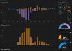
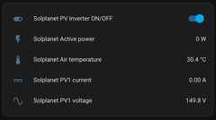
Result
Full local insight and control of your solar inverter.
Plus, you can now add this to your energy dashboard. I also have a dynamic energy contract for which I have an automation that automatically shuts down my solar panels if the price goes negative.